- 您现在的位置:买卖IC网 > Sheet目录1236 > PIIPM25P12B008X (Vishay Semiconductors)IC PWR MODULE PROG ISO 25A 1200V
�� �
�
�PIIPM25P12B008�
�I27147� 02� -� Oct�
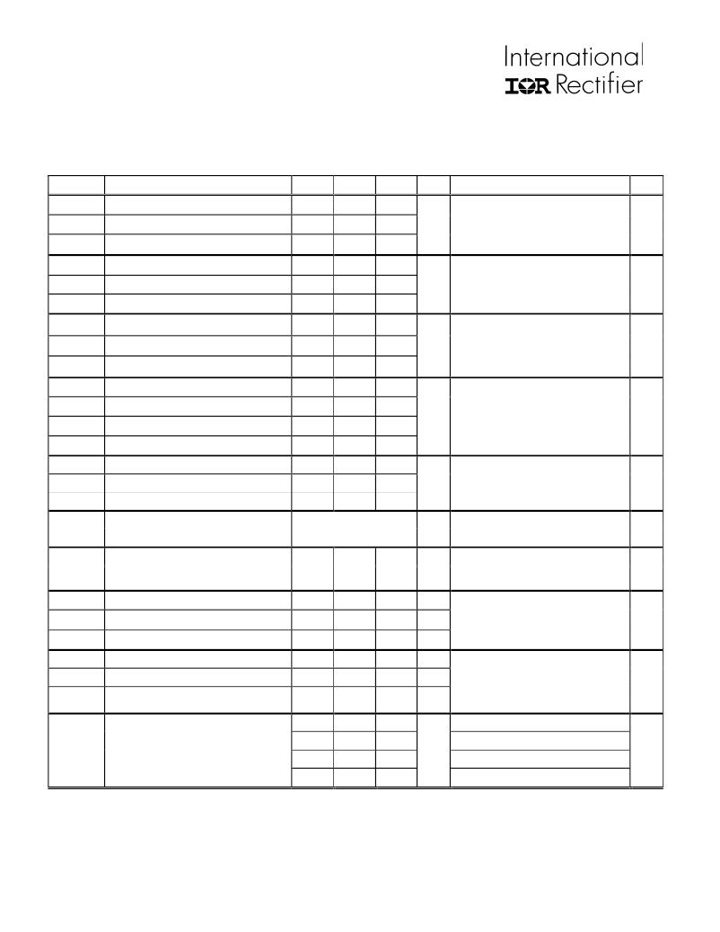
�Switching� Characteristics:� Inverter�
�For� proper� operation� the� device� should� be� used� within� the� recommended� conditions.�
�T� J� =� 25°C� (unless� otherwise� specified)�
�Symbol�
�Q� g�
�Q� ge�
�Q� gc�
�E� on�
�E� off�
�E� tot�
�E� on�
�E� off�
�E� tot�
�td� (on)�
�Tr�
�td� (off)�
�Tf�
�Parameter� Definition�
�Total� Gate� Charge� (turn� on)�
�Gate� –� Emitter� Charge� (turn� on)�
�Gate� –� Collector� Charge� (turn� on)�
�Turn� on� Switching� Loss�
�Turn� off� Switching� Loss�
�Total� Switching� Loss�
�Turn� on� Switching� Loss�
�Turn� off� Switching� Loss�
�Total� Switching� Loss�
�Turn� on� delay� time�
�Rise� time�
�Turn� off� delay� time�
�Fall� time�
�Min�
�Typ�
�169�
�19�
�82�
�1900�
�1300�
�3200�
�2700�
�2000�
�4700�
�192�
�33�
�213�
�210�
�Max�
�254�
�29�
�123�
�3600�
�2000�
�5600�
�4600�
�2300�
�6900�
�210�
�49�
�227�
�379�
�Units�
�nC�
�μ� J�
�μ� J�
�ns�
�Test� Conditions�
�I� C� =� 25A�
�V� CC� =� 600V�
�V� GE� =� 15V�
�I� C� =� 25A,� V� CC� =� 600V,� T� J� =� 25� oC�
�V� GE� =� 15V,� R� G� =22� ?,� L� =� 200� μ� H�
�Tail� and� Diode� Rev.� Recovery� included�
�I� C� =� 25A,� V� CC� =� 600V,� T� J� =� 125� oC�
�V� GE� =� 15V,� R� G� =22� ?,� L� =� 200� μ� H�
�Tail� and� Diode� Rev.� Recovery� included�
�I� C� =� 25A,� V� CC� =� 600V,� T� J� =� 125� oC�
�V� GE� =� 15V,� R� G� =22� ?,� L� =� 200� μ� H�
�Fig.�
�23�
�CT1�
�CT4�
�WF1�
�WF2�
�13,�
�15�
�CT4�
�WF1�
�WF2�
�14,16�
�CT4�
�WF1�
�WF2�
�C� ies�
�Input� Capacitance�
�2200�
�V� CC� =� 30V�
�C� oes�
�C� res�
�RBSOA�
�SCSOA�
�Output� Capacitance�
�Reverse� Transfer� Capacitance�
�Reverse� Bias� Safe� Operating� Area�
�Short� Circuit� Safe� Operating� Area�
�10�
�210�
�85�
�FULL� SQUARE�
�PF�
�μ� s�
�V� GE� =� 0V�
�f� =� 1MHz�
�T� J� =� 150� oC,� I� C� =100A,� V� GE� =� 15V� to� 0V�
�V� CC� =� 1000V,� V� p� =� 1200V,� R� G� =� 5� ?�
�T� J� =� 150� oC,� V� GE� =� 15V� to� 0V�
�V� CC� =� 1000V,� Vp=� 1200V,� R� G� =� 5� ?�
�22�
�4�
�CT2�
�CT3�
�WF4�
�E� REC�
�Trr�
�Irr�
�Diode� reverse� recovery� energy�
�Diode� reverse� recovery� time�
�Peak� reverse� recovery� current�
�1820�
�300�
�25�
�2400�
�32�
�μ� J�
�ns�
�A�
�T� J� =� 125� oC�
�I� F� =� 25A,� V� CC� =� 600V,�
�V� GE� =� 15V,� R� G� =22� ?,� L� =� 200� μ� H�
�17,18�
�19,20�
�21�
�CT4�
�WF3�
�Rth� JC_T�
�Each� IGBT� to� copper� plate� thermal� resistance�
�0.65�
�oC/W�
�Rth� JC_D�
�Rth� C-H�
�Each� Diode� to� copper� plate� thermal� resistance�
�Module� copper� plate� to� heat� sink� thermal�
�resistance.� Silicon� grease� applied� =� 0.1mm�
�0.95�
�0.03�
�oC/W�
�oC/W�
�See� also� fig.� 24� and� 25�
�24,25�
�52�
�I� C� =� 3.5A,� V� DC� =� 530V,� fsw� =� 8kHz,� T� C� =� 55� oC�
�PD1�
�Pdiss�
�Total� Dissipated� Power�
�70�
�114�
�102�
�W�
�I� C� =� 5A,� V� DC� =� 530V,� fsw� =� 8kHz,� T� C� =� 55� oC�
�I� C� =� 5A,� V� DC� =� 530V,� fsw� =� 16kHz� T� C� =� 55� oC,�
�I� C� =� 10A,� V� DC� =� 530V,� fsw� =� 4kHz,� T� C� =� 40oC�
�PD2�
�PD3�
�www.irf.com�
�7�
�发布紧急采购,3分钟左右您将得到回复。
相关PDF资料
PK3020KB
KIT KEYPAD, MOUSE, AND USB HUB
PK3021LI
KIT LIGHT, MOUSE, AND USB HUB
PK3022ET
KIT CAT5 CABLE MOUSE USB HUB
PKSERIAL-I2C1
BOARD DEMO PICKIT SERIAL I2C
PKSERIAL-SPI1
BOARD DEMO PICKIT SERIAL SPI
PL-BYTEBLASTER2N
CABLE PROGRAMMING PARALLEL PORT
PL-MASTERBLASTER
CABLE PROGRAMMING RS-232/USB
PL-USB-BLASTER-RB
CABLE PROGRAMMING USB
相关代理商/技术参数
PIIPM50E06A004
制造商:IRF 制造商全称:International Rectifier 功能描述:Programmable Isolated IPM
PIIPM50E06A004X
制造商:IRF 制造商全称:International Rectifier 功能描述:Programmable Isolated IPM
PIIPM50E06B004
制造商:IRF 制造商全称:International Rectifier 功能描述:Programmable Isolated IPM
PIIPM50E06B004X
制造商:IRF 制造商全称:International Rectifier 功能描述:Programmable Isolated IPM
PIIPM50E06C004
制造商:IRF 制造商全称:International Rectifier 功能描述:Programmable Isolated IPM
PIIPM50E06C004X
制造商:IRF 制造商全称:International Rectifier 功能描述:Programmable Isolated IPM
PIIPM50E06D004
制造商:IRF 制造商全称:International Rectifier 功能描述:Programmable Isolated IPM
PIIPM50E06D004X
制造商:IRF 制造商全称:International Rectifier 功能描述:Programmable Isolated IPM